We’re feeling the heat in the Midwest this weekend. The last couple of days have been cresting 90F pretty easily making it tough for a lot of yardwork. I did get the mowing done yesterday and then went to the park mid-day to see if I could get a training run completed in the heat – the Bix7 is less than a weak away. Thanks to the leg rehab and quite frankly a very comfortable season up to this point, the heat acclamation has not been up to par this year and it is showing on the long runs. A week ago Linda and some friends of mine piled into the car and headed up for a Bix@6 training run. That was definitely rough and hoping that doesn’t repeat on race day. Fortunately, I made it through the run, but I admittedly did take a mile off the distance due to the fact the human coolant system went dry capping off my sweat production. When that happens, it’s best to cut your losses and head back. I ended up feeling the after effects of that until early this morning. Long story short(er), I’m just kicking back, taking it easy today and figured it was a great time to introduce a new category called “What Is This” or WIT for short. Every once in awhile something comes along that is odd or interesting from a creative or mechanical perspective. To make it interesting for you, I’ll provide a number of pictures or clues in a blog post to help you figure it out. The answer will then be posted at the end of the NEXT blog entry. Are you up for the challenge?
The first WIT challenge is this:
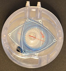
First some details that may or may not help you. This was found in the basement of Linda’s mother’s house while we were clearing it in order to fix some foundation problems she was having. It was just thrown in a pile of miscellaneous stuff and immediately fascinated me for a couple of reasons. One it looked complex and intricately designed. The other cool feature is there was a gear on the other side that rotated the rounded triangles in a unique pattern. It took a few days to figure out what it was (big thanks to Linda having some recollection in the distant past on what it was). As a hint, it is not really a toy, nor is it a working part for anything in the house … well, at least nothing in a typical house. It is also not an American design. There is one reader of this blog that might already know what it is, but the rest of you might want to check out the detailed assembly pictures that follow after the jump.
To help you out (and give you an impression as to why it caught my eye) I have taken a number of photos of it in varying disassembled states.
This is a side view of the object. As you can see, it is made of stacked plexiglass of varying colors, but all perfectly machined in a cylinder.
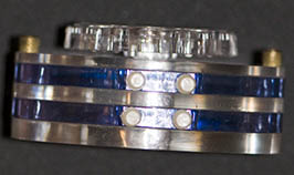
The top of it actually has a small gear on the top of it. When this gear is turned, the rounded triangles seen from the bottom view rotate in an off center manner. Note, the metal tab in the middle of the unit doesn’t really play into the mechanism beyond that it gives some leverage when screwing the plastic gear into the rest of the body.
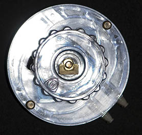
The following series of images represent the dis-assembly of the mystery object. I tried to do this one layer at a time so you can get a feel for it’s construction and also get an idea of how it might function when the top gear is rotated. For starters, here is the top gear that came off the assembly when the tabbed screw was removed. Essentially just a symmetrical circle with grip points that look like gears around the side. Also note, the center whole is square allowing it to grip onto the object it is rotating without slipping.
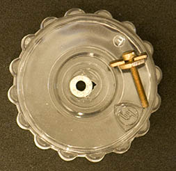
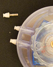
The plastic gear above sat on top of a solid piece of plexiglass about 1/8″ thick. There was a small section cut out of it which you can see in the upper left of the following picture. Two knobbed screws were also removed from each side. They were both copper looking and only had threads at the bottom portion of the object that screwed into the bottom plastic plate to hold everything together.
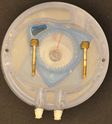
The top plat has been removed showing the first rounded triangle shape. As you can tell, it sits around a piece of plastic with a square head that fits into the gear top and therefore would be rotated when that top gear is moved. I forgot to take an image of this, but there is a gear on the underside of the top plate that the center of the triangle rotates around. The center plastic post actually sits in a circle cut out of the middle of the triangle. You might want to put on your thinking caps hear and try to visualize what it looks like when that gear is turned – note, the gear stays put, the triangle is moved around that middle gear due to the meshing of the gear teeth.
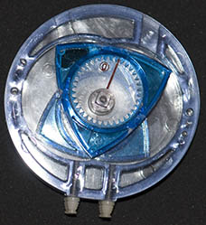
Here is a closer look at the triangle piece along with the interior plastic post (clear) which sits underneath the blue triangle. Basically visualize the triangle on top of the post with the post sticking through the top plastic circle. This plastic post also has a cut out that fits on a similar piece below it which forces that bottom post to rotate along with the top one. Also keep in mind that the post is not in the center of that clear plastic circle.
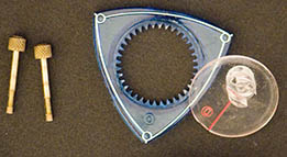
This is what it looks like with those objects removed.
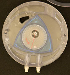
Although accidently turned, there is a plastic piece that the triangle rotates within. It is circular on the outside, but looks like it has two off-center circles cut out of the middle of it It did not come out well in the photo, but this layer is colored blue.
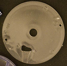
With that piece removed, there is another solid plate similar to the first one with the same cutout pattern on it. The center post of the gear below it sticks through the opening and hooks into the bottom of the plastic post shown above.
Once that is removed, you are then left with a duplicate rounded triangle layer with one difference. On this layer, the plastic center post is sitting on top of the triangle and not underneath it as in the earlier layer.
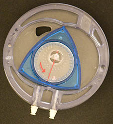
Just so you are clear, the clear center posts in each of the rounded triangles is smooth on both sides (no gear, no slots) and they fit exactly into the centers of the triangles. You would think they would just slide in the middle of the triangle and nothing would happen, however since the posts are off center, this combined with the gears on the solid plastic plates insures that they spin. That confused me at first, but after looking at it and trying different things to get it to rotate without spinning, I came to the conclusion that the off center placement is forcing the issue and since the triangle is locked into rotating within the blue plate, it has to turn.
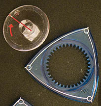
This is a duplicate blue plastic layer as before. It has the same shape as the first one, but is place upside down on the bottom plate.
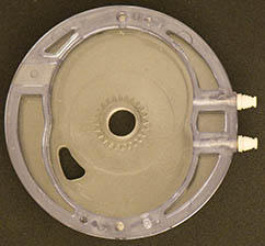
Lastly, we have the bottom plate. Here you can actually tell there is a small set of gears built into the center of the plate. This is the same way the first plate is built but again upside down so the gears are facing the interior of the object.
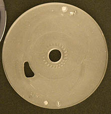
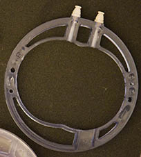
Oh, almost forgot. You probably noticed the four pins that stick out from the side of each of the blue plastic layers These all have a similar shape on the head and simply screw perpendicular into the ring. Actually, the ring is flattened slightly where these pins screw in. While writing this, it occurred to me that it could not be entirely perpendicular or the pins would slant outward slightly due to the curvature of the circle. (Note, I missed that when I was taking it apart)
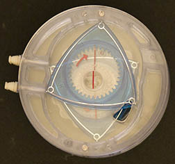
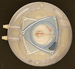
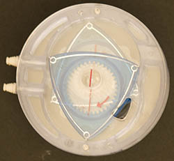
With that, you now have seen every layer of the construction. I wanted to leave you with another set of images that attempts to show how the triangles actually rotate together. To be honest, this is the part that intrigued me the most mainly at how odd, yet perfectly the triangles rotated in their off-center axis and they perfectly fit the double circle cut-outs in the blue layer. The person who invented this contraption had his geometry hat on for sure. So here is the rotation effect. Note, the first picture is slightly out of whack with the others. This was not intentional to throw you off or anything, just a lack of precision on my part. More care will be taken in future WIT posts. Straight left will be the starting point (or at least that was the intent). The red lines and arrow provide movement references.
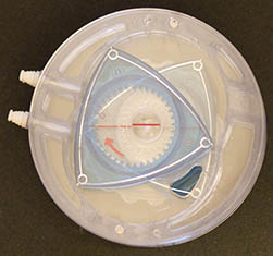
90 degrees clockwise to start
180 degrees clockwise to start
270 degrees clockwise to start
Well, that is all the pictures I have for you. The more I think about it, the more I convince myself to give another parting clue. At the beginning, I stated: “As a hint, it is not really a toy, nor is it a working part for anything in the house …” Let’s add some clarity to that. In essence, it is not a real working part (as in it isn’t a finished product used in the real world), but it IS a model of something that is developed, implemented and still sold in a certain type of industry. There are competing designs for this particular function and I would have to say this is probably the less common approach.
Good luck!


Maybe not exactly what the the model you have is, but the basic shape of the rotor and the chamber appears to be that of a model of a Wankel (rotary) engine. Used in the RX-7 for a while – not sure if it’s still in production though (possibly also some aircraft back in the day?). While it was very smooth and high revving engine, it was also very easy to damage by putting in incorrect spark plugs, and tended to consume quite a bit of oil while running. Plus, the high amount of “quench” areas make / made it hard to control emissions…
Skids, nicely played! You are exactly correct in that it is indeed a model of a Wankel (rotary) engine. I actually figured you had a good chance of recognizing it from your import car days, but I didn’t think it would be THAT easy. Linda’s father was the service manager for a Chrysler dealer in the Quad cities and apparently this was brought in as a marketing tool by a vendor or used as a training device although I am not sure that auto manufacturer every implemented one of these engines. So, the burning question is… did you put the wrong size of spark plug in a Wankel engine?
Dang, too late. A Wankel engine model for sure.
Ron
Geez, what do you people do all day, read Popular Mechanics? I find this thing the basement and spend hours trying to figure out what it is. I make a post of it and the next thing I know everybody’s inner Voc student jumps all over it. Unfortunately, I am not the best at automotive mechanics and in fact had a product mechanics class where I work and ended up with three extra bolts while rebuilding one of our engines…. knowing my place was in the office, I threw them in the oil pan and screwed it on the engine. Don’t panic, it was a training engine and never made it out of that room….
It’s still in production apparently…
http://www.mazdausa.com/MusaWeb/displayPage.action?pageParameter=modelsMain&vehicleCode=RX8#/performance/renesisRotaryEngine
And no, I never actually worked on one myself, so no engine catastrophies by yours truly. Once I got out of the Auto Tech program and got a job, I primarily worked on BMW and Volvo (the occasional Porsche, but the Porsche tech was pretty protective of his “cars”.)
As for only 3 bolts left over? One of the techs I used to work with would approve. This guy that always had extra parts. He knew exactly where they went, but would throw them aside and say, “You really don’t need this one… just makes it harder to service in the future.”